The WinCC OA
Channel Manager is a standalone module that hosts
a number of channels and devices of a client application (typically
driver). The Channel Manager "knows"
all its channels and devices. A device is a representation of
a piece of equipment in the field. The channel is the physical
interface (connection) to get to this device.
Each type of
connection is implemented by a plug-in. A plug-in is a piece of
software that is loaded by the Channel
Manager when specified in the configuration
file. Each plug-in implements the communication via a specific
channel. The first version of the Channel
Manager supports a plug-in called "MODEM", that is used to
communicate to N devices over a PSTN network (with or without
a terminal server) and a plug-in called "COM"
that is used for serial communication to a device.
The Channel
Manager communicates with a client application. A typical
client application is a software driver reading or writing data
from a remote telemetry device. The client application sends and
receives commands to and from the Channel
Manager. These commands
typically include:
"Connect" -> establish connection
to a physical device "Read" -> read (raw) bytes "Write" -> write (raw) bytes "Disconnect" -> client application
does no longer need the device
The following
figure shows how a driver (like the Dynamic Logic driver) and the Channel Manager work together to communicate
with N devices.
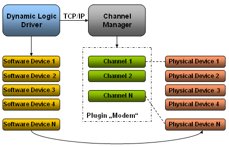
The
client application (driver) connects to the Channel
Manager and sends commands to the manager or listens on
the TCP/IP socket for incoming data. There is a single TCP/IP
connection between a client application and the server. Most messages
between client and server contain the readable name of channel
or device.
Typically, the
driver has a software definition of each device. When the driver
needs to communicate to the field, then the driver requests a
channel with a specified type. The Channel
Manager will look into his pool of channels/modems and
will allocate one to the driver. The driver then receives a "handle"
to the allocated and opened channel. The Channel
Manager closes the modem when the client application stops,
or when the client commands the Channel
Manager to disconnect the channel.
A channel can
work in two directions:
Outgoing - the connection
is established when the client application (the driver) asks
for it. Incoming - the modem is
waiting for an incoming call. Outgoing / incoming - the
modem is normally 'incoming' but will be used for outgoing
traffic when no outgoing modem is available.
 Note Note
Throughout this documentation the Dynamic Logic driver is used as
an example to illustrate the usage of the Channel
Manager since it is the first driver that uses it.
For the usage
of the Channel Manager the following
points have to be considered:
There
can be exactly one Channel Manager
running on one WinCC OA
system (in a redundant system there will be one Channel
Manager running on each of the controllers, but only
the active WinCC OA
controller is using the channels). The
single instance of the Channel Manager
has to manage all configured channels. Channels
cannot be shared among several WinCC OA
systems. Channel Manager and driver could
reside on different controllers as long as they are using
the same data and event manager (running on the same WinCC OA system).
Types of Connections
The Channel Manager
supports the following types of connections:
Redundancy
The Channel Manager
is able to run in a redundant configuration. This means
that a switchover is executed when serious errors are indicated.
The active server is able to use all modems
connected to the network (the modem racks connected to both servers).
This is technically no problem since all modems are on the Ethernet.
This is best illustrated in the following figure.
Active server A uses all modems in modem rack
A and modem rack B. The passive server always releases all modems
so that a "new" active server can again use all available
modems (and thus telephone lines).
Caution
The active server uses only channels (modems)
that are on the network. Modems connected to a physical port of
a computer cannot be shared. That means that Server A can not
use the modem assigned to the COM port of server A'.
Types of Plug-ins
The Channel Manager
module supports two types of plug-ins:
Note that the plug-ins "MODEM" and "COM" are not to be confused:
When a client application
(driver) commands "Connect Device" and the plug-in
is MODEM, then the Channel Manager will dial the device with
the configured phone number. It will wait for the connection
to be established and will then answer with "Device Connected". When a client application
commands "Connect Device" and the plug-in is COM,
then the Channel Manager will
open the physical port and answer with "Device Connected".
The plug-ins "MODEM" and "COM"
were implemented when developing the
Dynamic Logic driver. The Dynamic
Logic device can be connected to a computer via a modem
or via a direct serial cable. Connecting a device via the plug-in
COM is much faster because no phone calls need to be made.
The "MODEM" plug-in can also communicate
to a terminal server that supports the RFC2217 protocol (different
terminal server types are supported). This basically means that
every RS232 communication port has an associated TCP/IP port.
Sending data to the TCP/IP port means that the data goes out over
the serial line.
The only part of the RFC protocol that has been
implemented is sending a DTR to a modem during connection termination.
Note
The RFC2217 protocol specifies that baudrates,
parity and other settings can be set via this protocol. This,
however, is not used since the Channel
Manager assumes that the terminal server rack is pre-configured.
That means that baudrates and port settings are pre-configured
and stored in the terminal server.
The configuration is best shown in the following
figure:
Note that the "Westermo" modem is
an example. The Channel Manager
communicates to a modem attached to a COM port or to a modem connected
to a terminal server.
User Interface
The user interface of the Channel
Manager module consists of the device overview panel, the
channel overview panel and their settings and information pop-up
panels.
|