Modbus/TCP is an adaptation of the serial
Modbus protocol for TCP/IP communication. The Modbus/TCP driver
can be used for Modbus/TCP or UNICOS at the same time.
Modbus/TCP is used to read or write data blocks
on PLCs.
UNICOS is a CERN defined extension of Modbus/TCP.
A communication with UNICOS is only possible if necessary programming
is made in the PLC (see UNICOS,
basics).
The information exchange takes place via different
function codes (see Modbus/TCP
driver details). These function codes are part of the peripheral
address and have to be specified by the user.
Addressing
The peripheral address includes the following
points:
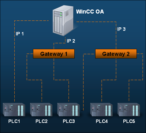
A unit address is required if several PLCs
hang on one LAN-Gateway with an IP address (e.g. for PLC 2 and
PLC 3). If the PLC has an own IP address the unit address should
be set to 1 - e.g. for PLC 1 (see Configuration
panel of the Modbus/TCP driver).
Since a PLC can be reached via several connections
more than one TCP/IP connection can be assigned to one PLC. Maximal
two connections to a PLC are supported. This means that two network
paths are possible.
Master/Slave and Client/Server
The Modbus protocol is based on a master/slave
topology. A master is the unit which initiates a bus transaction
(request) in the communication. The master sends the requests
and the slave responds to the requests. The slave may not send
requests. A slave can never become active. In a TCP/IP environment
the TCP client has to be the master since the client establishes
the connection. The TCP server is the slave. The slave makes a
"Listening Socket" and is able to respond to the connection
requests and further to the requests via this socket.
The driver can both modes (master and slave) at
the same time. The slave modus is needed to receive spontaneous
data, the master mode to send commands and requests (this means
that the driver establishes a connection with the periphery when
it wants to send or request values. The driver also opens a TCP
server socket at the same time. The socket allows the peripheral
devices to connect to the driver and send data spontaneously.)
The following figure shows the data flow for a
Modbus/TCP driver:
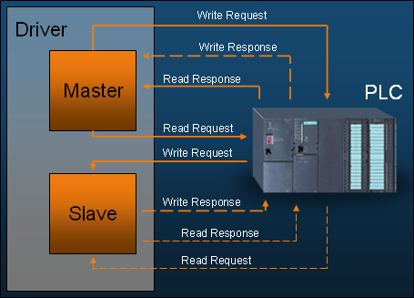
The master of the driver has to send a write request
in order to send data to the PLC. The response of the write request
is only relevant for the protocol layer. This is shown as dashed
lines in the figure above.
There are two possibilities for input data: the
master either sends a read request in order to query data from
the PLC or the slave receives a write request from the PLC.
The slave responds to the read request with "dummy"
data for simulation purposes. The query of meaningful data from
the driver is not supported because the WinCC OA
does not normally query the PLC data. |