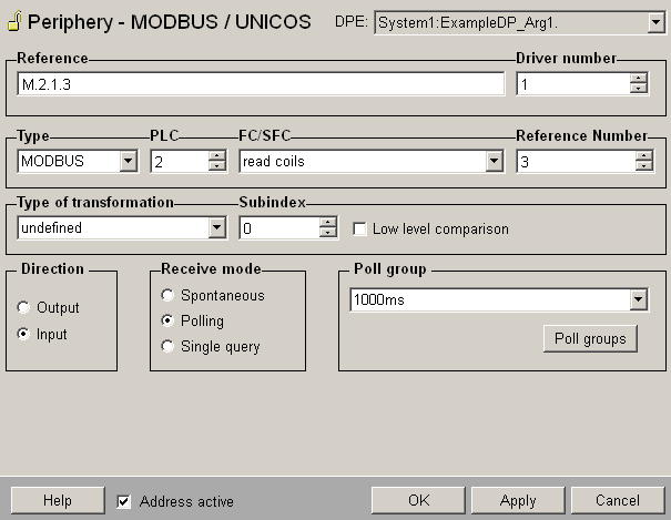
The
panel shown in the figure below allows the configuration of a
peripheral address for the Modbus/TCP driver.
You can enter the address directly in the
Reference
text field or create it with the spin buttons.
Figure: Panel for defining a peripheral
address for Modbus/TCP

Type
MODBUS or UNICOS.
PLC
Number of PLC that has been set on the internal data point
of the type _Mod_Plc
during configuration.
FC/SFC
The possible function codes. All combinations of function codes,
modes and addresses are not possible. The used function code
depends on the PLC in the slave mode of the WinCC OA driver. The allowed
values of the FC/SFC field are:
|
Output |
Input Polling |
Input Spontaneous |
MODBUS |
5
write coil
6 write single register
15 force multiple coils
16 write multiple register |
1
read coils
2 read input discretes
3 read
multiple register
4 read input register
7 read exception status
24 read FIFO queue |
5
write coil
6 write single
15 force multiple coils
16 write multiple coils |
UNICOS |
not
applicably |
not
applicably |
1
status
17 events32
(32 bit event frame)
18 events
(16 bit event frame) |
 Note Note
Assure that the used function codes are compatible
with the data types! The driver only checks the compatibility
of the function code with the transformation type.
 Caution Caution
By spontaneous input mode and function code
FC 15 (force multiple coils) only use reference numbers divisible
by 16 (an error message is shown when using numbers not divisible
by 16) . The sub index can lie between 0 and 1919. For all other
cases this modulo 16 limitation does not exist.
Type
of transformation
Choose the transformation
type of the Modbus driver from the combo box (see Reference
tables). The subindices for the Modbus are dependent on
the transformation type. If the current value is bigger than
the upper boundary when changing the type of transformation
the subindex is set to the new maximum value.
When a string is written, then only the number of bytes according
to the string length, inclusive the Zero at the end, is written.
If the transformation type "string"
or "blob" is used
for polling an input, the number of bytes can be set. For
example: M.1.3.10:100 polls 100 bytes beginning with the address
M.1.3.10. Note that the entry is only possible for "string"
or "blob".
Transformation type |
Maximum
subindex |
Possible function code |
boolean |
1919 |
FC 3 (read multiple registers)
FC 4 (read input registers)
FC 16 (write multiple registers)
FC 24 (read FIFO queue) |
char |
239 |
int16 |
119 |
uint16 |
119 |
int32 |
59 |
uint32 |
59 |
byte |
59 |
float |
59 |
boolean |
1919 |
FC 1 (read coils)
FC 2 (read input discretes)
FC 15 (force multiple coils) |
double |
29 |
FC 5 (write coil)
FC 6 (write single register)
FC 15 (force multiple coils)
FC 16 (write multiple registers) |
boolean
as byte |
0 |
FC 5 (write coil) |
boolean |
15 |
FC 6 (write single register) |
char |
3 |
int16 |
0 |
uint16 |
0 |
boolean |
7 |
FC 7 (read exception status) |
char |
0 |
 Note Note
In the driver versions before WinCC OA version 3.9 it was
important that several data point elements were summarized by
means of the subindex in order to guarantee efficient polling
queries. This is not longer required since version 3.9, but is
still supported due to compatibility reasons. When polling, the
driver automatically summarizes addresses to as optimal blocks
as possible.
Low level comparison
You can choose this option only when the transfer direction
is set to Input. If the option is chosen the data is only
sent in case of changes. The comparison is based on the raw
data without conversion.
Direction
Define if you want to send values of a data point element to
the command direction (output)or to the alert direction (input)
via the Direction radio buttons.
Receive mode
There are three different receive modes for the input: Spontaneous,
Polling or Single query.
Poll group
Choose already existing poll groups. If there are no poll groups
available you have to create them with the specific polling
parameters in an own panel. The panel is opened by clicking
on the Poll groups... button (see Poll
groups for more information on poll groups and polling
parameters).
Address active
The Address
active check box is chosen.
The address is used by the driver (see Reference tables).
An inactive address exists and the attributes can be set and
queried but the driver does not use them. This means that
no values can be sent to remote system or received from the
remote system for this data point.
OK:
Applies the settings or changes and closes the panel. Cancel:
Discards the settings or changes and closes the panel. Apply:
Applies the settings without closing the panel. Help:
Opens this page of the Online Help. |