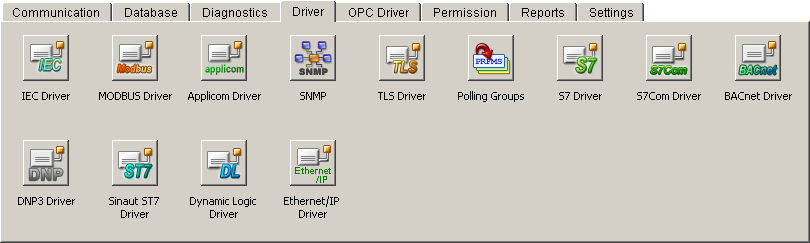
Driver
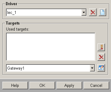
Lists the internal
driver data points. By default the internal data points _Iec_1,
_Iec_2 and _Iec_2 already exist. The commands (general query,
counter request, etc.) are sent to all connections. For each
IEC driver there must be
one of these DPs that the user must create, if it does not
exist by default.
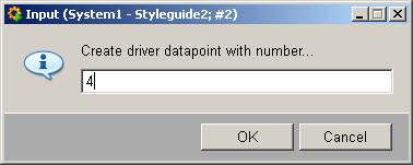
By clicking Create
and Delete a new DP
(also automatically the redundant (“_2”)) can be added/deleted
(this will be added / deleted only if the Apply
button was clicked). When creating the DP automatically the
next free driver number is proposed that can be taken over
or modified.
Connections
In the Connections
area all connection data points are listed that are configured
for this driver. With the buttons  and and
 a new connection
data points can be added or deleted. a new connection
data points can be added or deleted.
 Note Note
Only one data point can be added / deleted
at the same time. Only if the Apply
button was clicked, the next data point can be added.
Click on the  button
to configure the selected connection data point (see Configuration of the connection
data points below). button
to configure the selected connection data point (see Configuration of the connection
data points below).
Configuration of the connection data points
Figure: Configuration of the
IEC connections
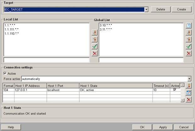
Target
Select here the data point name (connection
name) that should be configured from the combo box.
Click on Create
to create a new data point of the _IecConnection data point
type. (incl. redundant DP). The behavior is the same as for
the previous panel. Valid characters for a connection data
point are [a-z,A-Z,0-9,_]. In a redundant WinCC OA
project a data point with the name "<datapointName>_2" is created automatically.
Click on Delete
to delete the selected DP.
Click on Apply
to apply the creation/deletion.
Local List
Enter the addresses of the stations that
can only be accessed via this connection (see IEC driver, basics). The addresses
are specified in the text box below the lists. Format: "region.component.module.value.subaddress"
(= Common Address.Information Object Address, see also Panel for defining the peripheral
addresses of the IEC driver).
A value of "*" means "all values between 0
and 255".
The buttons allow you to insert, edit or delete (see Default
buttons).
Global List
Enter the addresses
of all stations that are not only accessible via this
station (Gateway1) but rather via other stations, too. This
saves you having to enter parameters several times for redundant
connections. In our example the same stations are also accessed
via Gateway2. So if you set the parameters for Gateway2 connections,
press  to open a panel and
copy the global lists from Gateway1 to the current data point
Gateway2. to open a panel and
copy the global lists from Gateway1 to the current data point
Gateway2.
 Caution Caution
With regard to addresses in the list, make
sure that you specify the address without a data type, while
the IEC bus address begins
with the data type (see Panel
for defining the peripheral addresses of the IEC
driver). This is particularly important with regard to
filtering by DPs!
Caution
Telegrams that are received from the PLC
and are not available in the global or local list but posses
a WinCC OA
address, are processed by the driver.
Note
If several connections, which contain same
addresses in the local or global list, are created the messages
are always sent via all paths. This means that the station
has to cope with the fact that it receives the messages more
than once.
Note
If you want to execute a general query
via the config entry autoGQ, _DriverCommon or _IecConnection
data point, no wildcard ('*') may occur in the Common Address
(first 2 bytes from left) in the Local/Global List!
Note
The distinction between Local List and
Global List does not play any role in the driver itself, for
which both lists are equivalent. The distinction in local
and global stations is only to facilitate configuration!
Caution
If in the peripheral address panel a connection
name won't be specified the driver only sends frames via a
connection if the station is in the local or global list,
otherwise the command is discarded!
Connection settings
Allows the configuration of separate "physical"
connections.
Active
Sets all configured connections to (in)active.
Force active
The behavior for selection of the redundant
connections can be configured via the combo box: either the
driver shall select a connection automatically or an explicit
connection can be selected. In the latter mode, a connection
switch-over does not take place even if the connection gets
lost. Therefore, all connections are listed in the combo box
(that are displayed in the table) and can be selected.
Table
In the table you can find all configured
connections. The first column indicates the IEC format (101
or 104) followed by the connection parameters in the next
columns. The next column displays the connection state. In
the last column you can set the connection active/passive.
The columns differ with respect to the IEC format.
Click on the button
to define the connection parameters for a new connection.
Click on the button
to change the parameters of the selected connection.
Note
Currently it is not supported to change
the IEC connection configuration at runtime.
Click on the button
to delete the selected connection from the table.
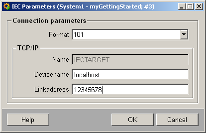
In case of IEC 101 only the device
name and the link
address can be set. The device name refers to a device_101 entry in the
config file. In addition, only one connection is allowed.
Thus, it is not possible (if there is already one available)
to add a new connection (button is grayed out). The parameters
can be set via the following panel:
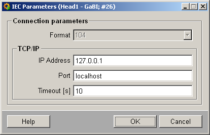
In case of the IEC 104 several connections
can be configured, but 101 and 104 may not be mixed. The parameters
that need to be set are IP
Address, Port and Timeout.
In the redundant
state the panel differs only by the table
and the connection status.
In a redundant state, the host and the redundant host as well
as the both ports are displayed.
The timeout
is the same for both. It is also not possible to set selectively
the redundant/non-redundant connection to active/passive.
Thus, also here only one check box is available. At the bottom
the both connection states of the corresponding connections
are displayed.
Status
Displays the (DP global) communication
state (States.ConnState):
0: Communication
error 1: Communication OK
and started 2: Communication OK
but not yet started 3: Connection deactivated > 4: Connectionstate
undefined
|