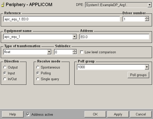
The
panel shown in the figure allows to configure a peripheral address
for the Applicom driver.
The address is created with the aid of the
single components (Equipment
name combo box, Address text field). The peripheral
address is finally visible in the text field Reference and contains the device
name that was defined for a specific device. The driver determines
all other important parameters for the access to the device via
Applicom like channel, protocol, card and device number via this
device name.
Figure: Definition of an Applicom
peripheral address

 Caution Caution
If you configure an address, which contains
a device that did not have an address when the driver started,
the address does not work (the status of the device in the configuration
panel for the Applicom driver remains "Starting" ).
The addresses configured afterwards work first after a re-start
of the driver (an appropriate message is displayed in the log
viewer). Otherwise you can configure addresses online and they
are directly available without a re-start of the driver. Note
that you have to be located in the address space of spontaneous
data when configuring spontaneous input data online (see also
Access functions and polling).
Type
of transformation
Choose the transformation type from the combo box. The transformation
type is the interpretation of the data that was read on the
peripheral device. The transformation always has to match
with the address (if e.g. 4 bytes are read from the PLC the
type of the transformation has to be float or int32). For
more information on the transformations see chapter Details
on the Applicom driver.
Subindex
Using word oriented PLCs (e.g. Siemens S5) you can access bytes
within a word with the Subindex functionality.
 CAUTION CAUTION
Note that you cannot have two identical active
outputs. If you try to configure two identical outputs, an error
message is shown: WCCOANV (2),
2007.07.04 15:22:14.697, PARAM,SEVERE, 47,
Duplicate peripheral address for this output, DP: System1:dyn_struct_2.three:_address.._reference,
MAN: (SYS: 1 Event -num 0 CONN: 1).
Receive mode
The receive mode for the input is spontaneous, polling or single
query.
Poll group
Choose already existing poll groups. If there are no poll groups
available you have to create them with the specific polling
parameters in an own panel. The panel is opened by clicking
on the Poll groups...
button (see Poll
groups for more information on poll groups and polling
parameters).
 Note Note
A change of the poll group or the first use
of a poll group during runtime of the driver, requires a re-start
of the driver!
 Note Note
The Applicom poll list should be used at poll
times < 1 second. Synchronization times are not supported when
using the Applicom poll list. If a synchronization time is defined
in a poll group the Applicom driver takes care of the polling
function automatically.
With the config entry MaxInternPollTime (see
also Possible config entries
of the Applicom driver) you can define what else should be
polled with card polling (Default is 10 seconds). With poll times
< 5 seconds the synchronization time is ignored. For all elements
over this time and having a defined synch. time, driver polling
is used.
|