Open the configuration panel of the Applicom
driver via the System management panel:
Figure: System management - Drivers tab
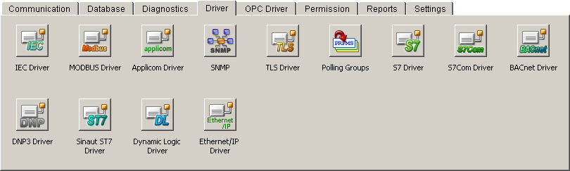
Click on the Applicom
driver button. Configure the periphery in the following
configuration panel. You have to configure the peripheral device
that is connected directly with the card and contains essential
data like card number, channel number and device number. An internal
data point of type _Apc_Equ
is created per device - Applicom also mentions equipments instead
of device - (see also Internal
data points of the Applicom driver). Also if the peripheral
device is configured redundant, only one internal data point is
used when creating the equipment.
Figure: Configuration panel of
the Applicom driver
The configuration panel for the Applicom driver
is divided into two areas. In the upper area you define the Applicom
equipment and the settings for this equipment:
Create
Open another dialog windows for creation of a new device (in
case of a redundant project a data point with device name
+ "_2" is created automatically for each
device data point - the *_2 data points are not visible in
the selection). After creating the device the further parameters
can be set for the peripheral device. These are saved in an
internal data point. If you want to change the settings, choose
the device from the combo box, specify e.g. another channel
number and click on Apply.
 Note Note
Modified settings will be active first after
a re-start of the driver. Merely the check box "Active"
when configuring the connection as well as the settings for device
resp. connection configuration (see description below) can be
changed at runtime.
Remove
Removes the chosen device. A dialog box opens in which you
can confirm the deletion.
Protocol
Sets the protocol. The communication with the periphery/device
takes place via this protocol. You can choose only the protocols,
which were defined in the Applicom configuration file, from
the combo box. (see also Rules
of the address transformation).
Applicom
poll list
Activates the internal polling of the Applicom card for this
device (the check box is activated by default). Maximum of
255 cyclic functions can be executed per channel when polling
with the internal Applicom poll list. A cyclic function is
a read request. The data is read from the periphery with the
cyclic function (for more information on cyclic functions
see chapter Access functions
and polling). If the value 255 is exceeded the polling
takes additionally place via the driver (this means that the
Applicom driver uses the classes implemented in the general
driver for the polling function). The internal card polling
of Applicom provides the benefit of cyclic functions. The
administration of cyclic functions runs on an own CPU and
does not affect the performance of the computer the WinCC OA is running on.
General Query
Activate this check box if you want to execute a general query
to the peripheral device. The check box is activated by default.
If this option is activated (see also the config entry AutoGQ on the page Possible
config entries of the Applicom driver) general queries
are executed when the driver starts or always when the connection
to the device is established. If the check box is not active
no general query is executed for this device. A general query
for a peripheral device can also be executed when the driver
is running. Therefore you have to set the Equipment Id (=
a unique number assigned from the driver) on the internal
data point of the driver (data point is of type _DriverCommon).
Further information on this possibility you can find on the
page Internal data points
of the Applicom driver.
Redundant device
Activate this check box if the peripheral device is configured
redundant. If this check box is activated, the appearance
of the configuration panel changes, i.e. in the lower area
of the panel, where the connection is configured, two additional
tabs are visible: Redundant
device and Device
configuration.
Redundant connection
Activate this check box if the peripheral device has a redundant
connection to the process control system. If this check box
is activated, the appearance of the configuration panel changes,
i.e. in the lower area of the panel, where the connection
is configured, two additional tabs are visible: Connection 2 and Connection configuration.
Note
The configuration of a redundant connection
is independent of a possibly existing redundant device and vice
versa (you do not need a redundant connection in order to configure
a redundant device)!
Info ...
Clicking on this button opens another panel, which shows status
information of the configured devices and the connection.
If the project is configured redundant, the statuses of both
computers are displayed.
In the lower part of the panel you configure the
settings for the connection (redundant/not redundant) to the peripheral
device (redundant/not redundant). If the device and the connection
is configured redundant, the panel looks like in the following
figure (the checkboxes Redundant
device and Redundant connection
described before have to be activated of course):
The name of the "main tab" is the host
name (in the figure above eiwrk017).
If the WinCC OA
project is additionally configured redundant, a tab for the redundant
partner is also visible.
On the tab First
device you have to configure Connection 1 and 2. The tab
Redundant
device is identical to First
device. Make the following settings for each device resp.
connection:
Board
Number
Specifies the number of the Applicom card. The device is accessible
via the number. Up to eight cards can be installed per computer.
Channel
Number
Specifies the channel number (can be equated with the number
of the physical interface) on the Applicom card. The communication
with the periphery takes place via this channel. Maximum four
channels (0-3) can be set per card. The number of channels
is dependent on the used hardware (Applicom card). If the
Applicom card has e.g. a network and a serial interface, it
has two channels. Furthermore, a connection to 128 peripheral
devices (0-127) with different protocols can be established
on each channel.
Note
The definition of cards, channels, and device
numbers takes place already when configuring the Applicom board.
For more information on the numbers see "Topic configuration"
in the Applicom Online Help. Redundant devices/connections are
independent devices in the Applicom configuration. The connection
of these only takes place in WinCC OA.
 Caution Caution
When configuring client (can only be used for
spontaneous data) and server (for writing resp. querying of values)
equipments in the Applicom console, you have to consider, that
the device number of both is different, even if it is the same
physical device!
Active
Choose the check box in order to set the peripheral device
to active or inactive. You can deactivate a device that is
already created and configured. This way the address space
on the Applicom card is available for other peripheral addresses.
The device (data point) is not deleted and can be reactivated
at any time. The status display changes from "Connected"
to "Not Active"
if a device is deactivated.
Status
Shows the status of the connection to the periphery. There
are five possibilities "Not
Connected" (Connection to the peripheral
device lost e.g. PLC was disconnected from the network; stop
the Applicom driver in the console), "Connected"
(Connected with the peripheral device), "General
Query" (General query runs), "Not
Active" (Device with the associated check box
set to inactive. If no connection to the device is detected
when the driver starts, this message is shown and the driver
changes to "Not Connected" after the first
alive monitoring) and "Fifo
Full" (Event queue overflow). The computer name
is displayed before the status, e.g. "eiwrk017:
Connected".
Active connection
This display at the bottom of the configuration panel acts
as overview in case of redundant devices. If you switch between
redu/single devices data points, this last info row is visible
resp. not visible.
If the settings for the connection to the periphery
are configured, you have to configure
the device on the tab of the same name (the configuration
of the devices only has to be done if the devices are redundant).
Which settings, described in the following sentences, are necessary
for the configuration, depends on the realization of the redundant
PLCs. On this tab you have the following possibilities for configuration:
Command
to active device, Command to both devices
Here you can define to which device a command from the control
system (send direction) should be sent. A command can only
be sent to the active device or to both devices.
Automatic,
Device
1, Device
2
In this area you make settings for messages to the control
system (receive direction) in case of redundant devices. Automatic
defines, that the driver decides which device is active when
polling of values. The decision is made by sending of alive
messages (only the active device can be used for polling).
With the setting Automatic
and the definition of a PLC Tag (see below) the
driver checks the defined tag (address in the PLC) which shows
whether the device is active or passive. With the setting
Device
1 resp. Device 2 you make a fix
definition of the active device, which provides data to the
driver.
Caution
If either device 1 or device 2 is configured
as active and this device falls out, no messages can be sent to
the control system. Use this setting only for test purposes!
PLC
Tag
In this text field you can configure a tag in the PLC (e.g.
a bit in the address space of the PLC) which signaled the
active device in case of redundancy (1=Active, 0=Passive).
The input of the address of this tag has to correspond with
the syntax of the selected protocol for the communication
with Applicom and the periphery. An example for the correct
input of a tag, with syntax of the Industrial Ethernet S7
protocol, you can see in the figure above (see also setting
of the protocol in the upper area
of this configuration panel). The driver checks this tag when
polling of data and thus it knows the active device. Furthermore
you have to consider that the settings for the receive direction
made before are over-configured when defining a PLC tag, i.e.
if you have configured Device 1 resp. Device 2, this setting
will be ignored and only the PLC tag has relevance.
If the connection
to the devices is configured redundant you have to configure the
connection on the Connection
configuration tab:
The settings you can make on this tab are the same
as described before on the Device configuration tab. The difference
of these settings is the configuration of redundant connections,
contrary to redundant devices. Furthermore you have to consider
that if you define a PLC tag when configuring the connection,
the interpretation of the driver is different. The tag defines
again an address in the PLC (e.g. a bit). The value of this bit
finally defines the connection which the driver selects, e.g.
0 is the first connection, 1 is the second connection. The value,
i.e. the selected connection, can be different on the devices. |