The relevant differences between S7 and S5 PLCs
concerning the WinCC OA
drivers are:
Requirements
In order to communicate with a Siemens S5 PLC via
TCP/IP either a CP1430-TCP or a S5Lan Adapter from ”Process
Informatik” (www.process-informatik.de) is required. The
S5Lan adapter is plugged directly into the S5 programming interface.
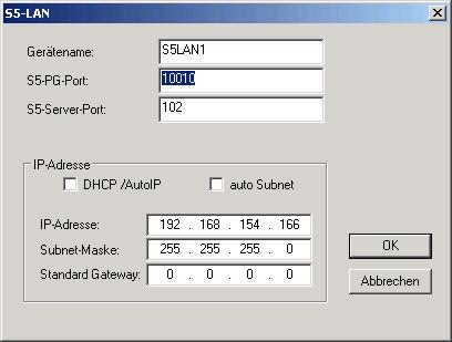
 CAUTION CAUTION
Note that the S5 server port of the S5 LAN manager
ALWAYS has to be set to 102 (See figure below).
Figure: S5 LAN manager
Configuration
The S5 specific entries and the handling of the
internal data point _S7_Config are described in this section.
For the S5 connection, the new configuration is described in the
following table:
Information |
Type |
Send Local TSAP |
string |
Send Remote TSAP |
string |
Receive Local TSAP |
string |
Receive Remote TSAP |
string |
|
These are the TSAPs that must match the settings
in the S5 PLC. For the communication via a S5Lan adapter these
settings can contain arbitrary values.
Figure: Panel for configuration
of a connection to a Siemens S5 PLC
Information on the internal DPE
The Rack, Slot and the TSPPExtras DPEs are not
used for the S5 communication. The information of the S5 connection
is contained in the ConnectionType DPE of the _S7_Config DPT.
For a S5 connection the value must be 256 (the bit 8 has to be
set to one).
The new TSAP elements are combined into a string
DPE s5TSAPs in the form:
”<SendLocalTSAP>.<SendRemoteTSAP>.<ReceiveLocalTSAP>.<ReceiveRemoteTSAP>”
Each TSAP string can contain maximum 8 characters.
Addressing differences between the S7 and S5 PLC
Data Block Organization
The difference between S5 and S7 address layout
is that the data block (DB) addresses are 16bit word based, on
the contrary to the S7 equipment, that is byte based. There are
also some differences in the syntax of the addresses (see table
below). This is relevant for the address selection in the address
panel. The bit number in a DB address e.g. does not run from 0
to 7 but from 0 to 15.
Table: S7 and S7 PLC addresses
S7-300
/ S7-400 variable (corresponds to the address in the para
panel) |
S5
variable (corresponds to the address in the para panel) |
Type
of exchange |
WinCC OA transformation
type |
My.z |
My.z |
read
/ write bits |
boolean |
DBx.DBXy.z |
DBx.Dy.z |
read
/ write bits1 |
boolean |
E(I)y.z |
E(I)y.z |
read
input bits |
boolean |
A(Q)y.z |
A(Q)y.z |
read
/ write output bits1 |
boolean |
MBy |
MBy |
read
/ write bytes |
byte |
DBx.DBBy |
not allowed |
read
/ write bytes |
byte |
E(I)By |
E(I)By |
read
input bytes |
byte |
A(Q)By |
A(Q)By |
read
/ write output bytes |
byte |
MWy |
MWy |
read
/ write words |
int 16/uint 16 |
DBx.DBWy |
DBx.DWy |
read
/ write words |
int 16/uint 16 |
E(I)Wy |
E(I)Wy |
read
input words |
int 16/uint 16 |
A(Q)Wy |
A(Q)Wy |
read
/ write output words |
int 16/uint 16 |
MDy |
MDy |
read
/ write double words |
int 32/uint 32 |
DBx.DBDy |
DBx.DDy |
read
/ write double words |
int 32/uint 32 |
MDyF |
MDyF |
read
/ write floating words |
float |
DBx.DBDyF |
DBx.DDyF |
read
/ write floating words |
float |
Tn |
Tn |
read
/ write timers |
uint 16 |
Zn |
Zn |
read
/ write counters |
uint 16 |
|
The S5 PLC cannot access individual bits. This
means that the writing of individual bits is not possible and
an error message is shown.
Limitations for S5 Support
The following limitations are valid for the communication
to S5 PLCs via the WinCC OA
native S7 driver:
No TSPP is supported for
the S5 equipment. Only one connection for
reading and writing is established to the S5 PLC (i.e. useConnections
config entry is not concerned). Reading of the PLC Time,
PLC operation state and the time synchronisation of the PLC
is not supported. No symbolic addressing is
supported for S5 PLC. Addressing of arrays through
a basic address on the node is not supported.
Example for S5 Configuration using CP1430TCP
Figure: WinCC OA
S5 configuration when using CP1430TCP

|