Click
on the address config of a data point element, select the driver
type NATIVE SIMATIC S7 from the
combo box and click on the button "Configure"
.... The opened panel, shown in the next figure, allows
a configuration of peripheral address for the S7 driver.
The address is created with the aid of the
single components (Connection
name combo box, Address combo box, Spin-buttons
x, y
and z). The peripheral
address is finally visible in the text field Reference and contains the connection
name that was defined for a specific device and the symbolic address
or the S7 protocol address. The driver determines all other important
parameters for the access to a specific device via this connection
name.
Figure: Definition of an S7 peripheral
address
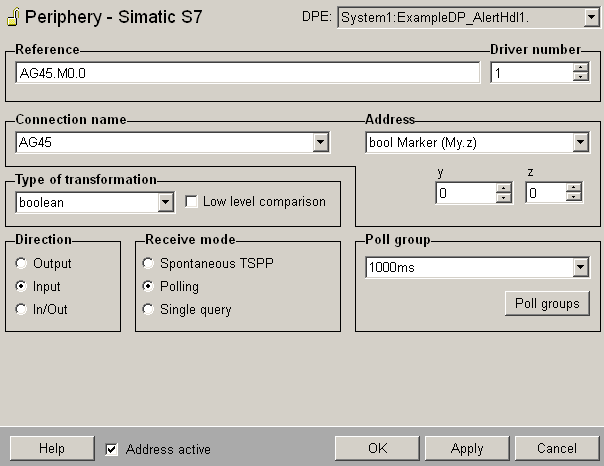
Address
Define here the address that is assigned to the data point
element at the peripheral device. As shown in the figure above
a read/write bit with the address "M0.0"
on a Siemens Simatic S7 is configured for the data point element
TestDP03.bool. The
reference is composed of the configured device and the address.
The address can be configured with symbolic addresses (in
this case open the symbol editor via the button "..."
which is visible in the address area when selecting the option
Symbolic address from the
combo box - see also Symbolic addresses
for further details on this symbol editor) or you can use
the S7 protocol specific addresses (select the desired address
from the combo box and specify the x, y or z component for
the address with the Spin buttons below - you can find the
possible S7 data types and the type of transformation in WinCC OA in a table at
the end of this page).
The selected address is put into the field Reference
of the address panel and has the following form:
<Connection name>.<Symbolic address> resp.
<Connection name>.<S7 specific
address>
The addresses can also be set directly in the field Reference
without the aid of the single components described before.
The value in the Reference field is checked automatically.
Type of transformation
Choose the transformation type from the combo box. The transformation
type is the interpretation of the data that was read on the
peripheral device. The transformation always has to match
with the address (if e.g. 4 bytes are read from the PLC the
type of the transformation has to be float
or int32). If the address is defined via the combo box and
Spin buttons also the correct type of transformation for the
specific address will be selected automatically.
If the type default is selected
in the combo box, the driver determines the transformation
type automatically, depending on the value in the field Reference.
For symbolic addresses the mapping in the corresponding data
point of type _S7_Symbolics
will be checked automatically.
If you click on OK
or Apply in the PARA panel,
the panel checks whether the transformation type and the value
in the field Reference fit (according to the table, at the
end of this page, if the type is not default).
For reading/writing a string either symbolic addresses or byte
addresses from the table (at the end of this page) can be
used. When writing a string only the number of bytes corresponding
to the string length including the terminating 0 are written.
When polling an input using the transformation type "string"
the number of bytes can be set e.g. DB100.DBB10:100 polls
100 Bytes beginning from the address DB100.DBB10. Note that
you can specify the number only for the transformation type
String.
You can find the possible S7 data types and the type of transformation
in WinCC OA
in a table at the end of this page.
 Note Note
When writing a value of type TIME,
note that the reference string has to point to the first target
data block!
Note
Using symbolic addresses you have to check
that the type of transformation is correct and not set to "default"!
Note
When the values of a data point element are
sent in both directions (In/Out), then this data point element
must not be directly subordinated to a struct node (structure
of values).
Receive mode
The receive mode for the input can be Spontaneous
TSPP, Polling or Single query. Spontaneous TSPP
can only be used if Use TSPP
has been activated in the S7 configuration panel for the corresponding
connection.
Poll
group
Choose already existing poll groups. If there are no poll groups
available you have to create them with the specific polling
parameters in an own panel. The panel is opened by clicking
on the Poll
groups... button (see Poll
groups for more information on poll groups and polling
parameters).
Possible WinCC OA
data types
The following WinCC OA
data types can be used to define peripheral addresses for the
S7 driver:
char, unsigned, int, float, bool, bit32,
string, dateTime array char, array unsigned, array int,
array float, array bool, array bit32, bitString
Possible S7 data types
In an S7-300 or an S7-400 the following data types
with the following names for the addresses are available: |